Technical Information & Troubleshooting
Problem
Description
Cause
Solution
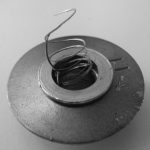
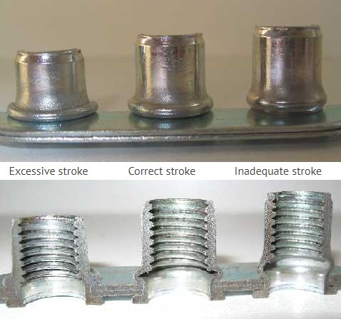
Stripped thread
- Over-stroked installation
- Damaged mandrel
- Excessive material thickness
- Low engagement with installation mandrel
- Reduce stroke
- Replace mandrel
- Check fastener effective grip range
- Ensure full thread engagement prior to installation
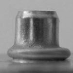
Tilting insert
- Damaged or bent mandrel
- Oversized or irregular hole
- Incorrect anvil on installation tool
- Replace mandrel if damaged
- Inspect and ensure hole size is correct and clean
- Ensure the correct matching anvil size is used
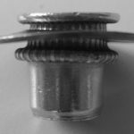
Turning insert
- Oversized or irregular hole
- Insufficient stroke
- Overgrip fastener used
- Inspect and ensure hole size is correct and clean
- Increase stroke on tool
- Check fasteners effective grip range
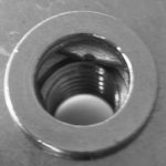
Internally buckled insert
- Overstroked installation
- Oversize hole with excessive stroke
- Irregular hole
- Overgrip fastener used
- Reduce stroke on installation tool
- Inspect and ensure hole size is correct and clean
- Check fasteners effective grip range
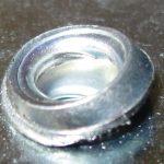
Scratched/indented head
- Incorrect anvil on installation tool
- Ensure the correct matching size anvil is used
Correct setting of of a Nut Insert
Problem
Description
Cause
Solution
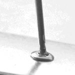
Mandrel not broken
- Material thickness too small
- Soft material
- Oversized or irregular hole
- Incorrect tip on installation tool
- Check effective grip range of fastener
- Check for fastener suitability and adjust grip range
- Ensure hole size is correct and clean
- Ensure the correct size and style tip is utilised
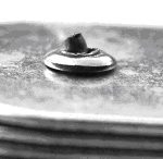
Part of mandrel protruding
- Damaged or bent mandrel
- Soft material
- Oversized or irregular hole
- Incorrect anvil on installation tool
- Check effective grip range of fastener
- Check for fastener suitability and adjust grip range
- Ensure hole size is correct and clean
- Ensure the correct size and style tip is utilised
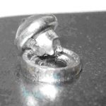
Rivet head not retained
- Oversized or irregular hole
- Insufficient stroke
- Overgrip fastener used
- Check effective grip range of fastener
- Ensure hole size is correct and clean
- Ensure tooling is capable of installing the fastener (beware work hardening stainless steel)
- Ensure the correct size and style tip is utilise
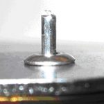
Mandrel breaks mid-length
- Overstroked installation
- Oversize hole with excessive stroke
- Irregular hole
- Overgrip fastener used
- Check effective grip range of fastener
- Ensure tooling is capable of installing the fastener (beware work hardening stainless steel)
- Ensure the correct size and style tip is utilised
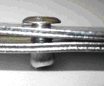
Lack of clamping on materials
- Incorrect anvil on installation tool
- Check effective grip range of fastener
- Ensure hole size is correct and clean
Galvanic Corrosion
This occurs when two metal elements having a different electric potential are directly and continuously connected to each other in the presence of an electrolyte (BATTERY).
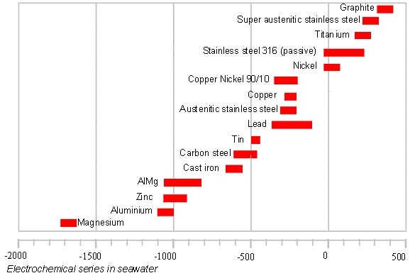
The electrochemical process thereby generated produces an electric current which causes the corrosion of one of the two electrodes, the one made of the “less noble” metal (that is, the one with higher electronegativity, the anode), while the other, the cathode, is protected.

It should be noted that the more aggressive an environment is, the greater the corrosion will be. Moreover, in the case of small surfaces the process is more marked.
Below is a table which shows the electrochemical series in seawater, that is, under particularly aggressive conditions.
HOW TO PROTECT A STRUCTURE AGAINST GALVANIC CORROSION?
Use materials in contact that are of the same nature or sufficiently close to each other in the galvanic series.
Or else adopt the following solutions

Chemical Corrosion
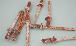
Oxidation is a natural phenomenon that occurs when there is contact between an oxygen-rich atmosphere and a metallic material. Corrosion is the effect of chemical and electrochemical phenomena which cause the destruction or deterioration of the metallic material.
Corrosion protection becomes one of the most important aspects to consider, especially in a fastening system, when designing a joint in particularly aggressive environments.
Until a few years ago, hexavalent chromium was one of the basic components of electrolytic zinc coatings. Numerous directives – RoHS; WEEE and ELV – have banned the presence of heavy metals such as lead, mercury, cadmium, PBB or PBDE and hexavalent chromium.
Each type of product has a specific zinc coating, which is conceived for its most common applications and indicated in the technical datasheet of the individual fastener by means of the symbols adopted by the leading European auto makers.
Zinc coatings other than the ones provided can be used, subject to a technical feasibility assessment. The resistance of a zinc-based surface coating can be increased using a sealant.
There are also other possible anticorrosive treatments for rivets and inserts, such as:
- Nickel plating
- Zinc-Nickel plating
- Copper-plating
- Etc.
Corrosion resistance is evaluated with a salt fog test. This is an accelerated corrosion test for qualitatively assessing the corrosion resistance of the protection provided by the coating.
There is no way of directly comparing the results of this test and the actual behaviour of the product once applied due to the numerous factors that influence corrosion, for example: whether the environment is highly oxidizing or not, the nature of the materials in contact, component deformation, which may partly ruin the surface coating layer, etc.
For such reasons it is not possible to guarantee any specific corrosion resistance beforehand.
However, for a wholly approximate indication, reference can be made to the following table:
|
Coating type
|
Electrolytic zinc plating | Number of hours in the salt fog chamber (naked-eye assessment of outer surface) |
|
| White rust on zinc | Red rust on zinc | ||
| FeZn 5 II | Bright light-coloured passivation | 24 | 72 |
| FeZn7II | Bright light-coloured passivation | 24 | 96 |
| FeZn7IV | Iridescent passivation | 96 | 168 |
| FeZn7IV S | Iridescent passivation with sealer | 120 | 360 |
Finally, it is advisable not to use components that have been zinc plated at temperatures above 250°C, as they are subject to degradation, albeit partial, of the zinc coating layer.
